In comparison to frog, reptile has some additional capabilities:
-
In addition to instructions, Reptile can also transfer data from/to the arbitrary locations in memory. Note that frog do also have some limited capacity to transfer data from (but not to) memory, but this data is very specific: It must be embedded in an LDI instruction. Hence, reptile programs are formed from two areas: a code area and a data area (Later on, we will also add a stack area to these). In order to interact with the data area, reptile has two additional instructions: Load (LD) and Store (ST). Load brings data from memory to a register, and store transfer data from a register back to memory.
-
Control flow: It can jump. The jumps can be conditional or unconditional, hence we need to have a flag register.
Hence, in total, we will add five more instructions to FISH’s ALU-based instructions.
In this chapter, we will investigate these new instructions from a software point of view. Thein hardware implementation will be given in later chapters.
1. Basic Architecture of Reptile
Reptile has the following specifications:
- 16 Bit data bus
- 12 bit address bus. Processor can address 4K of memory.
- 4 general purpose registers (GPR’s). Will be expanded to 8 later.
- 4 special purpose registers: Program Counter (PC), Instruction Register (IR), FLAGS register. Stack pointer (SP) and stack-related operations (PUSH, POP, CALL, RET) will be added later.
1.1 Software view of Reptile
A software programmer sees our hardware as follows:

(PC 14-bit olmalı)
Our hardware consists of two chips: A CPU and a memory chip. The CPU consists of
- A register bank that consists of 4 16-bit general purpose registers (GPR’s)
- A Program counter (PC)
- A 1-bit flag register
Of course, there are other details in the CPU such as an Arithmetic Logic Unit, an instruction register, multiplexers etc, but a programmer need not know about their existence, and in this chapter we are only concerned with the details that will interest a programmer. These details will be explained in detail at hardware chapters.
Two addressing modes will be used:
- Register indirect: Uses the contents of a general purpose register as a pointer to a memory location(used by load\/store instructions)
- PC relative: Adds the offset contained in the instruction to the contents of PC to obtain a pointer to a memory location (used by jump instructions)
2. Difference between assembly language and machine code
In order to understand what is coming, the student must remember the difference between the assembly language and machine code.
3. Instruction set
Our CPU will have 7 different type of instructions, given in the table below:
| Opcode (In hexadecimal) | Opcode Mnemonic | Instruction |
|---|---|---|
| 1 | LDI | Load Immediate |
| 2 | LD | Load |
| 3 | ST | Store |
| 4 | JZ | Jump if zero |
| 5 | JMP | Unconditional Jump |
| 6 | Unused | Unused |
| 7 | ADD, SUB, AND, OR, NOT, XOR, MOV, INC, DEC | ALU Operations |
Each instruction corresponds to a 16-bit number (except LDI, which corresponds to a 32-bit number). The first four bits of every instruction is known as the “opcode field”. The opcode field indicate the type of instruction.
Later on, we will add the instructions PUSH, POP, CALL and RET to the list above. Note that all these instructions require a stack, and therefore we have to implement a stack and a SP register before implementing them.
Below, we will explain how each instruction works.
3.1 Format of the LD\ST instructions
Load and Store instructions are known as “memory transfer instructions”. Load brings data from memory
In assembly language, these instructions are written as
LD x y
ST x y
where x and y are numbers between 0 and 3. Examples are
LD 1 2
ST 0 3
LD 3 3
LD x y will
- Find the memory location whose address is contained in register y
- Transfer the contents of that memory location into register x.
The instruction ST x y does just the reverse, ie
- Find the memory location whose address is contained in register x
- Transfer the contents of register y to that memory location.
A useful aid to memory is: Recall that in C\/C++ assignments the data always travels from left to right, ie, in count=x, the value of the variable x is transferred to the variable count. Similarly, in LD and ST operations, the register that determine the source is always at the right and the the register that determine the destination is always at the left.
The machine code for these instructions are 16-bits long and has the following format:
d in the figure means “don’t care”, as usual. In our examples we will always fill don’t care locations with 0’s (and never with 1’s) for consistency, even though this does not matter in practice.
Example: To illustrate the passage from assembly language to machine code, we give some assembly language LD\/ST instructions on the left and their machine code translations in hexadecimal on the right:
| Assembly | Machine code |
|---|---|
| LD 2 1 | 200A |
| LD 3 2 | 2013 |
| LD 2 2 | 2012 |
| ST 3 1 | 3058 |
| ST 1 3 | 30C8 |
| ST 3 2 | 3098 |
Note that the same register can be both source and destination. LDI 2,2 will load into register 2 the data whose address is in register 2.
1.4.2 Format of the LDI instructions
The assembly language format for the LDI instruction is
LDI r x
r denotes one of the general purpose registers, therefore it is a number between 0 and 3. x is the 16-bit immediate data that is to be loaded to this register. It can be in one of the three different formats:
- If x is a string, it denotes the address of a variable or a label.
- If it denotes the address of a variable, there should be a corresponding declaration on the .data section (.data section will be explained later), where the string x must be declared. For example, if we use LDI 2 COUNT, and if COUNT is a variable, then, in the .data section, we must have some declaration like COUNT: 5, where 5 is the initial value of the variable count. LDI 2, COUNT will not load 5 into reg2, but the address of the memory location where 5 is stored.
- On the other hand, if we have LDI 2, LOOP, and if LOOP is a label, there must be some instruction in the program labeled with LOOP, and the address corresponding to this label will be loaded into register 2.
- Note that in assembly language both LOOP or COUNT are strings, while in machine code they must be 16-bit (in case of variable) or 12-bit (in case of label) numbers. The conversion between strings and numbers is done by the assembler.
- LDI 2 40 will load the decimal value of 40 into reg2
- LDI 2 0x40 will load hexadecimal value of 40 into reg2.
The machine code format of LDI instruction is as follows:

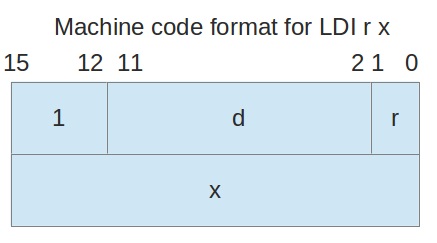
Example: Some assembly language LDI instructions are given on the left and their machine code translations in hexadecimal are provided on the right:
| Assembly | Machine code |
|---|---|
| LDI 2 0x1A | 1002 001A |
| LDI 3 0x2BA4 | 1003 2BA4 |
| LDI 2 count | Not possible to translate into machine code till theassembler resolves the symbol “count” |
| LDI 0 78 | 1000 004E |
| LDI 3 -47 | 1003 FFD1 |
1.4.3 Format of the JZ\/JMP instructions
The assembly language format for JZ\/JMP instructions are
JMP x
JZ x
where x is a string which is a label in the program (More on labels later). So, if we use the instruction
JMP LOOP
then LOOP must be defined as a label somewhere in the program.
The machine code formats of JMP\/JZ instructions are as follows:

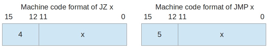
Note that in assembly language x is a string, while in machine code x is an 12 bit number. The conversion between these two forms is done by the assembler, according to the formula (address of the label)-(address of JUMP\/JZ instruction)+1. The operation is done in twos complement notation, and if the label occurs before the JUMP\/JZ instruction, we get a negative result.
1.4.4 Format of the Arithmetical and Logical instructions
There are 9 Arithmetical\/Logical instructions. Their assembly language format and meaning is summarized in the following table:
| ASSEMBLY | EXPLANATION | C EQUIVALENT |
|---|---|---|
| ADD r1 r2 r3 | Adds registers r2 and r3, puts the result into register r1 | r1=r2+r3 |
| SUB r1 r2 r3 | Subtracts register r3 from register r2, puts the result into register r1 | r1=r2-r3 |
| AND r1 r2 r3 | Ands registers r2 and r3, puts the result into register r1 | r1=r2&r3 |
| OR r1 r2 r3 | Or’s registers r2 and r3, puts the result into register r1 | r1=r2 | r3 |
| XOR r1 r2 r3 | Xor’s registers r2 and r3, puts the result into register r1 | r1=r2^r3 |
| NOT r1 r2 | Negates the contents of registers r2, puts the result into register r1 | r1=!r2 |
| MOV r1 r2 | Transfers the contents of registers r2 into register r1 | r1=r2 |
| INC r1 | Increments the contents of registers r1 | r1++ |
| DEC r1 | Decrements the contents of registers r1 | r1– |
Each ALU instruction has an associated ALU CODE, which is a 4-bit binary number. Note that as we have 9 ALU instructions, ALU CODE must be at least 4 bits wide
| Instruction | ALU CODE |
|---|---|
| ADD | 0000 |
| SUB | 0001 |
| AND | 0010 |
| OR | 0011 |
| XOR | 0100 |
| NOT | 0101 |
| MOV | 0110 |
| INC | 0111 |
| DEC | 1000 |
ALU CODE field identifies the mathematical operation performed by the instruction. As 9 operations, this field mus be at least 4 bits wide.
a) Machine code format of INC and DEC instructions
These are single argument instructions. Their machine code format is:


b) Machine code format of MOV and NOT instructions
These are two argument instructions. Their machine code format is:


c) Machine code format of ADD, SUB, AND, OR, XOR instructions
These are three argument instructions. Their machine code format is:
