0. Introduction
In comparison to frog, reptile has some additional capabilities:
-
Reptile can transfer data between arbitrary locations in memory and registers. Note that frog do also have some limited capacity to transfer data from (but not to) memory, but this data is very specific: It must be embedded in an LDI instruction. Hence, reptile programs are formed from two areas: a code area and a data area (Later on, we will also add a stack area to these). In order to interact with the data area, reptile has two additional instructions: Load (LD) and Store (ST). Load brings data from memory to a register, and store transfer data from a register back to memory.
-
Control flow: It can jump. The jumps can be conditional or unconditional, hence we need to have a flag register.
We will add four more instructions to Frog’s instruction set.
In this chapter, we will investigate these new instructions from a software point of view. Their hardware implementations will be given in later chapters.
1. Basic Architecture of Reptile
Reptile has the following specifications:
- 16 Bit data bus
- 12 bit address bus. Processor can address 4K of memory.
- 4 general purpose registers (GPR’s). Will be expanded to 8 later.
- 3 special purpose registers: 12-bit Program Counter (PC), 12-bit Instruction Register (IR), 1-bit FLAGS register. Stack pointer (SP) and stack-related operations (PUSH, POP, CALL, RET) will be added later.
Note that in frog we had 8 registers, but in reptile we have reduced that number to 4. The reasons for this will become apparent when we discuss reptile’s version of the ALU instruction below.
2. Software view of Reptile
A software programmer sees Reptile’s hardware as follows:

(PC 12-bit olmalı)
Our hardware consists of two chips: A CPU and a memory chip. The CPU consists of
- A register bank that consits of four 16-bit general purpose registers (GPR’s)
- A Program counter (PC)
- A 1-bit flag register
Note that in frog we had 8 registers, but in reptile we have reduced that number to 4. The reasons for this will become apparent when we discuss the ALU instructions below.
Of course, there are other details in the CPU such as an Arithmetic Logic Unit, an instruction registe,r multiplexers etc, which are not shown in Fig. xxx. A programmer need not know about their existence, and in this chapter we are only concerned with the details that will interest a programmer. These details will be explained in detail at hardware chapters..
Reptile instruction set consists of 6 instructions:
- Load Immediate (LDI)
- Load (LD)
- Store (ST)
- Jump (JMP)
- Jump-if-zero (JZ)
- Arithmetic-Logic (ADD, SUB, AND, OR, EXOR, MOV, NOT, INC, DEC)
We have already encountered Load immediate and Arithmetic-Logic instructions in our previous designs. The remaining four instructions, namely Load, store, jump and jump-if-zero, are new. We will learn about them in this chapter..
Two addressing modes will be used:
- Register indirect: Uses the contents of a general purpose register as a pointer to a memory location(used only by load\/store instructions)
- PC relative: Adds the offset contained in the instruction to the contents of PC to obtain a pointer to a memory location (used only by jump instructions)
The new instructions will force onto us some new software concepts. Load/store instructions necessitate the concept of variable, while the jump/jump if zero instructions necessitate the concept of label. Also, the concept of variable will necessitate a “data area” for our program, in addition to the code area. These will be investigated in the next chapter.
With six instructions, Reptile needs an opcode field at least three bits wide. But as we will add some more instructions later, we will allocate four bits to the opcode field to cover this future eventuality.
| Opcode (In hexadecimal) | Opcode Mnemonic | Instruction |
|---|---|---|
| 1 | LDI | Load Immediate |
| 2 | LD | Load |
| 3 | ST | Store |
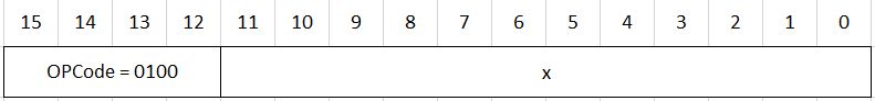
| 4 | JZ | Jump if zero |
| 5 | JMP | Unconditional Jump |
| 6 | Unused | Unused |
| 7 | ADD, SUB, AND, OR, NOT, XOR, MOV, INC, DEC | ALU Operations |
Each instruction corresponds to a 16-bit number (except LDI, which corresponds to a 32-bit number). The first four bits of every instruction is known as the “opcode field”. The opcode field indicate the type of instruction.
Later on, we will add the instructions PUSH, POP, CALL and RET to the list above. All these instructions require a stack, and therefore we have to implement a stack and a SP register before implementing them.
Below, we will explain how each instruction works.
3. Old Instructions: LDI and ALU
We have already covered Load immediate instruction (LDI) and Arithmetic-Logic instructions (ADD, SUB, AND, OR, EXOR, MOV, NOT, INC, DEC) when we have discussed Invertebrate, fish and frog. Hence we will not explain them in detail again. We will just point to the modifications they will undergo to get adapted to Reptile.
3.1 Load immediate (LDI) instruction
The assembly language format of the LDI instruction of reptile is the same with frog:
LDI r, x
which loads 16-bit number x into the register r. Here r is a register number, which is between 0 and 3. x is an 16-bit number. It can be written in decimal or hexadecimal notation.
The machine code for the LDI instruction in Reptile differs significantly from the same instruction in frog. Below, machine code fields of a LDI instruction located in memory address A is given.

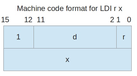
In the above figure, d means don’t care.. As a convention, we fill such fields with zeros, but any bit pattern can be used.
The opcode field for the LDI instruction is 0x1.
Note that LDI instructions are 32 bit long, and they occupy two consecutive words in memory..
Example: Some assembly language LDI instructions are given on the left and their machine code translations in hexadecimal are provided on the right:
| Assembly | Machine code |
|---|---|
| LDI 2 0x1A | 1002 001A |
| LDI 3 0x2BA4 | 1003 2BA4 |
| LDI 1 0x0 | 1001 0000 |
| LDI 0 78 | 1000 004E |
| LDI 3 -47 | 1003 FFD1 |
3.2 Arithmetic-Logic Unit (ALU) instructions: (ADD, SUB, AND, OR, EXOR, MOV, NOT, INC, DEC)
As in Frog, there are 9 Arithmetical\/Logical instructions. Their basic properties are listed below:
| ASSEMBLY | EXPLANATION | C EQUIVALENT |
|---|---|---|
| ADD r1 r2 r3 | Adds registers r2 and r3, puts the result into register r1 | r1=r2+r3 |
| SUB r1 r2 r3 | Subtracts register r3 from register r2, puts the result into register r1 | r1=r2-r3 |
| AND r1 r2 r3 | Ands registers r2 and r3, puts the result into register r1 | r1=r2&r3 |
| OR r1 r2 r3 | Or’s registers r2 and r3, puts the result into register r1 | r1=r2 | r3 |
| XOR r1 r2 r3 | Xor’s registers r2 and r3, puts the result into register r1 | r1=r2^r3 |
| NOT r1 r2 | Negates the contents of registers r2, puts the result into register r1 | r1=!r2 |
| MOV r1 r2 | Transfers the contents of registers r2 into register r1 | r1=r2 |
| INC r1 | Increments the contents of registers r1 | r1++ |
| DEC r1 | Decrements the contents of registers r1 | r1– |
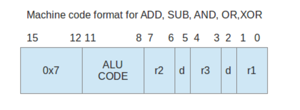
Machine code representation of the ALU instructions in Reptile are different from their previous versions in Frog. Each ALU instruction has
1) a 4-bit opcode field, which is 0x7 for all ALU instructions.
2) A 4-bit ALUCODE field. The ALUCODE field identifies the mathematical operation performed by the instruction. As there are 9 ALU operations, this field mus be at least 4 bits wide. ALUCODE’s of various instructions are listed below:
| Instruction | ALU CODE |
|---|---|
| ADD | 0000 |
| SUB | 0001 |
| AND | 0010 |
| OR | 0011 |
| XOR | 0100 |
| NOT | 0101 |
| MOV | 0110 |
| INC | 0111 |
| DEC | 1000 |
a) Machine code format of INC and DEC instructions
These are single argument instructions. Their machine code format is:


b) Machine code format of MOV and NOT instructions
These are two argument instructions. Their machine code format is:


c) Machine code format of ADD, SUB, AND, OR, XOR instructions
These are three argument instructions. Their machine code format is:
4. New Instructions : load, store, jump and jump if zero
Reptile will add two additional capabilities to the basic Frog design:
- Data transfer between an arbitrary location in memory and arbitrary register. This is achieved by the load (LD) and store (ST) instructions.
- Capability of jumping within a program: Jump (JMP) and Jump if zero (JZ) instructions.
4.1 Data Transfer Instructions: Load (LD) and Store (ST)
Note that the capacity of frog to transfer data between memory and CPU registers is severely restricted.
Frog has some capability to transfer data from a memory location to a register via the LDI instruction. But this data must be encapsulated within the LDI instruction itself. Frog does not have the capability to transfer data from an arbitrary location in memory into a register.
Frog totally lacks the capability to transfer data in the opposite way, ie, from a register back to a given memory location.
To address this deficiency, we will add two new instructions, Load (LD) and Store (ST) to the Reptile instruction set.
Load (ld) instruction
Load instruction transfers
- the contents of a memory location (which is a 16-bit number)
- into a register of Reptile.
The assembly format of the Load instruction is as follows:
LD r1 r2

Here r1 and r2 are two-bit fields denoting two registers:
- r1 is the register which will receive the data from memory.
- register r2 contains the memory address whose contents is to be transferred into the register r1.
Or, r1 <- M[r2].
Example: We want to load the contents of the memory location 0xF17 into register 3. This can be done as follows:
           ldi 2 0xF17
           ld  3 2
As a result, the contents of M[0xF17] is transferred into register 3. The previous contents of registers 2 and 3 will be lost. Actually, we can generate the same effect by
           ldi 3 0xF17
           ld  3 3
In this case, only the previous content of register 3 is lost.
Store (st) instruction
Store instruction stores
- The contents of a register
- Into a memory location, which is pointed by an another register.
The assembly format of the Store instruction is as follows:
ST r1 r2
 Here r1 and r2 are two-bit fields denoting two registers:
- r1 is a register which “points” to memory: It contains the address of the memory location to which the data is to be loaded .
- r2 is the register which contains the data to be stored in memory.
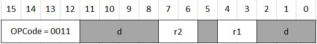
Machine code for ld and st instructions
The machine code for these instructions are 16-bits long and has the following format: d in the figures mean “don’t care”, as usual. In our examples we will always fill don’t care locations with 0’s (and never with 1’s) for consistency, even though this does not matter in practice.
Example: To illustrate the passage from assembly language to machine code, we give some assembly language LD\/ST instructions on the left and their machine code translations in hexadecimal on the right:
| Assembly | Machine code |
|---|---|
| LD 2 1 | 200A |
| LD 3 2 | 2013 |
| LD 2 2 | 2012 |
| ST 3 1 | 3058 |
| ST 1 3 | 30C8 |
| ST 3 2 | 3098 |
Note that the same register can be both source and destination. LDI 2,2 will load into register 2 the data whose address is in register 2.
field points to memory
field points to reg to write
field points to reg to read
4.2 Control Flow Instructions: Jump (JMP) and Jump if zero (JZ)
For any programming language to be useful, it must have the capability to loop through the code. The “while” and “for” statements in C/C++ are for this purpose.
Reptile will be able to “jump” within the code, conditionally and unconditionally. To accomplish this, we will have two new instructions: Jump (JMP) and “jump if zero” (JZ) instructions. JUMP and JZ instructions will enable us to write “for” and “while” loops we are familiar from high level languages in assembly.
- JMP instruction is unconditional: it always jumps to the given target location within the code
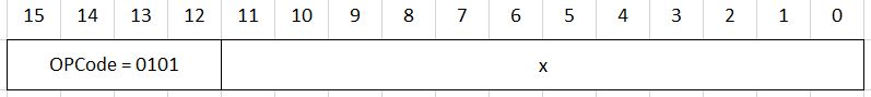
- JZ instruction is conditional: it jumps to the given target location within the code only if the result of the last ALU instruction is zero. Otherwise, the next instruction in the program is executed.
Frog did not have the capability to jump within the code. After an instruction is finished executing, always the next instruction is executed.
In the rest of this chapter we will investigate these new instructions in detail and give examples of their use. In the next chapter, we will examine how the assembler needs to be modified to handle these instructions and how the hardware of the frog is to be modified to incorporate than.