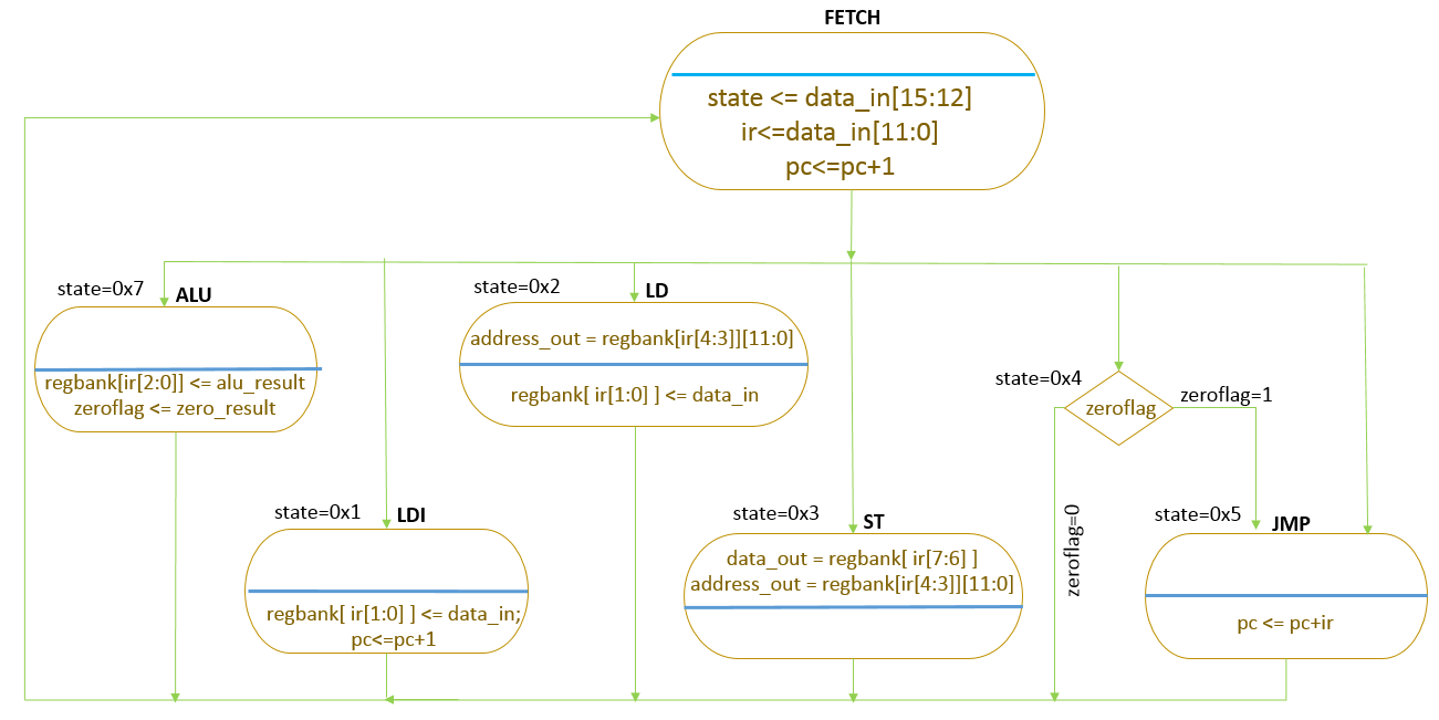
Reptile-4 FSM
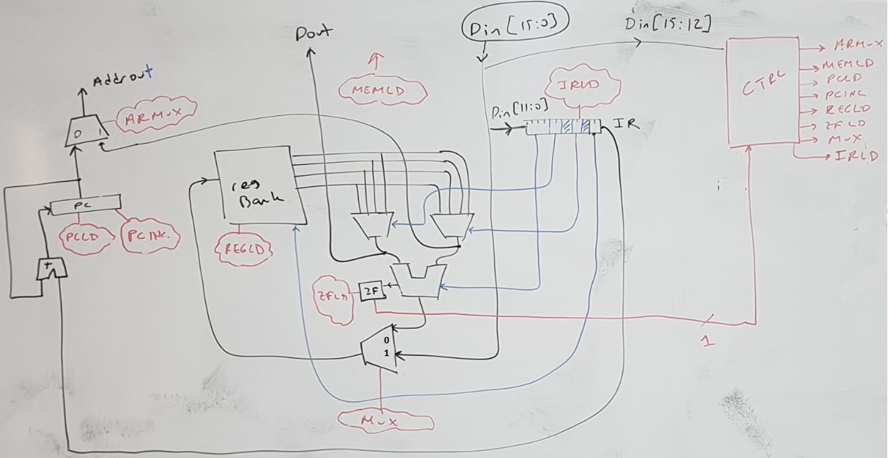
Reptile-4 Hardware

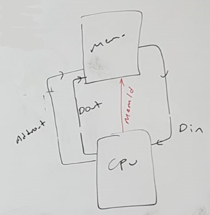
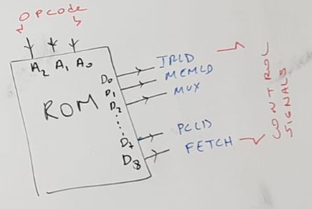
Reptile memory connection

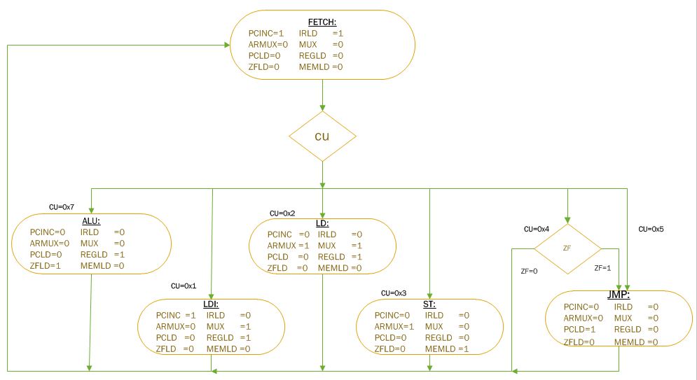
Reptile-4 FSM with Control Signals

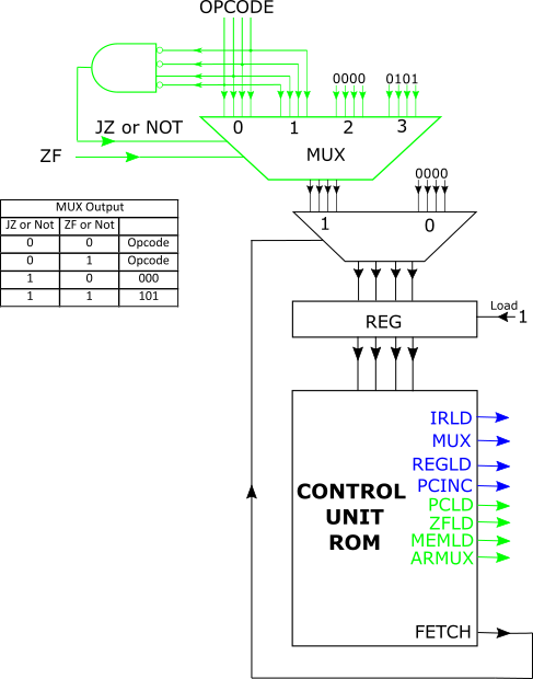
Reptile Control Unit
We must have as many lines as the number of “balls” plus one line for JZ.
Each line contains as many bits as control signals plus one bit for Fetch.

The complete circuit for the control unit of Reptile is shown below. As can be seen, it is almost identical with the control unit of Frog. The only difference is the part drawn in red in the diagram below, which handles the conditional jumps, ie, the JZ instructions.
 Hardware Design of Reptile Control Unit
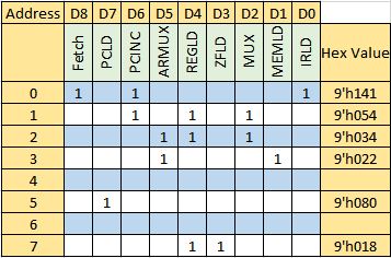
Microcode

Reptile in System Verilog
module reptile (
input clk,
input [15:0] data_in,
output logic [15:0] data_out,
output logic [11:0] address_out,
output logic memwt
);
logic [11:0] pc, ir; //program counter, instruction register
logic zeroflag; //zero flag register
logic [3:0] state; //FSM
logic [15:0] regbank [3:0]; //registers
logic [15:0] alu_result; //output for result
logic zero_result; //zeroflag value
localparam FETCH=4'b0000,
LDI=4'b0001,
LD=4'b0010,
ST=4'b0011,
JZ=4'b0100,
JMP=4'b0101,
ALU=4'b0111;
always_ff @(posedge clk)
case(state)
FETCH:
begin
if ( data_in[15:12]==JZ)
if (zeroflag)
state <= JMP;
else
state <= FETCH;
else
state <= data_in[15:12];
ir<=data_in[11:0];
pc<=pc+1; //increment program counter
end
LDI:
begin
regbank[ ir[1:0] ] <= data_in;
pc<=pc+1;
state <= FETCH;
end
LD:
begin
regbank[ ir[1:0] ] <= data_in;
state <= FETCH;
end
ST:
begin
state <= FETCH;
end
JMP:
begin
pc <= pc+ir;
state <= FETCH;
end
ALU:
begin
regbank[ir[2:0]] <= alu_result;
zeroflag <= zero_result;
state <= FETCH;
end
endcase
always_comb
case (state)
LD: address_out = regbank[ir[4:3]][11:0];
ST: address_out = regbank[ir[4:3]][11:0];
default: address_out = pc;
endcase
assign memwt=(state==ST);
assign data_out = regbank[ ir[7:6] ];
always_comb
case (ir[11:8])
4'h0: alu_result = regbank[ir[7:6]]+regbank[ir[4:3]];
4'h1: alu_result = regbank[ir[7:6]]-regbank[ir[4:3]];
4'h2: alu_result = regbank[ir[7:6]]®bank[ir[4:3]];
4'h3: alu_result = regbank[ir[7:6]]|regbank[ir[4:3]];
4'h4: alu_result = regbank[ir[7:6]]^regbank[ir[4:3]];
3'h5: alu_result = !regbank[ir[4:3]];
3'h6: alu_result = regbank[ir[4:3]];
3'h7: alu_result = regbank[ir[4:3]]+1'h1;
3'h8: alu_result = regbank[ir[4:3]]-1'h1;
default: alu_result=16'h0000;
endcase
assign zero_result = ~|alu_result;
initial begin;
state=FETCH;
pc = 0;
end
endmodule
Problems
- Add an overflow flag into hardware. How you should change the instruction set to take advantage of this new flag?
- Add address offset to load and store instructions.
- Create conditional jump instructions for many different conditions, ie, not only JZ but JNZ, JEQ, JGT etc.
- Increase memory size to 64K while keeping the data size 16 bits. Which instructions will change?
- Add a monitor which shows the address and PC at each instruction.